Note:
- These instructions are the same for the Bowden and direct drive plates. The instructions show the stock setup (1_LeftV3.6_Bowden.stl + 1_RightV3.6.stl). Even though the plates of the direct drive setup look a bit different, the installation steps are the same, with a DDE setup you can simply skip the reinstallation of the extruder.
- Depending on your setup you might have to remove the PSU to have acsess to the plates. I also uploaded a new PSU hoder to mount the PSU to the bottom 4040 profile. To save some filament you could also drill a few holes on the stock mount.
1. Plate Assembly
a) Nut Installation (Both Sides)
Insert two M3-Nuts in the back of the plates as well in the slot on the front.
b) Secure the nuts (Both sides)
To keep the nuts in place you can temporarily fix the Belt-Clamps (2_TensionerClampV3.stl) with two M3x12mm and the Belt Block (2_TensionerBlockV3.stl) with a M3x25mm screw.
2. Plate Installation
a) Remove Leadscrew Plate
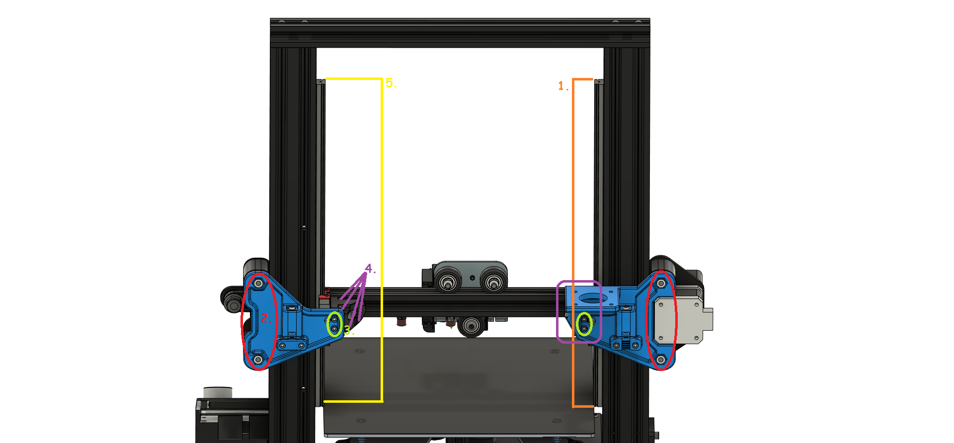
First you have to remove the old plate with the leadscrew nut, the outer M5x40mm screws and all V-Wheels. To get to the M5-Nuts more easily you can first dismantle the extruder. You will need it again on the new plate later if you want to build a Bowden setup.
c) Remove the V-Wheels on the right side
Remove the outer M5x30mm screws and all V-Wheels. Now you should be able to remove the whole axis from the printer.
ㅤ
ㅤ
ㅤ
ㅤ
ㅤ
ㅤ
e) X-axis preperation
The inner M5 screw must also be removed. Loosen the M4 screws that hold the metal plates to the X axis (on the right side you just need to remove the inner M4). After removing the M4 screws you can take out the M5. Use the M4 screws to fix the printed MGN parts ( 1_Left.stl and 1_Right.stl) to the plates. As already indicated, the right side (1_Right.stl) needs only one M4 screw, but the left side needs both. Make sure that the printed parts and the metal plates are flush with the top of the X-axis profile. Fully tighten these screws. Also put the printed spacers on the outside and “fix” them with the M5x40mm screws (these parts are only loosely put together, the M5 nut will be added in the next step).
f) Mount the Plates
Finally, the plates must be mounted. Insert 4 M3 nuts into the MGN parts (1_Left.stl and 1_Right.stl). Make sure that they are inserted with one corner first and pushed all the way to the bottom. Now attach the plates. Screw two M3x20mm screws per plate through the plates, into the nuts you just inserted into the MGN parts. Fix the outer M5x40mm screws you inserted loosely into the spacers with M5 nuts. (The extruder is shown here for reference only. Mount it (if needed) after all screws have been tightened in the next step.)
b) Rotate X-Motor
Loosen/Remove the 4 screws that are underneath the sticker on the X-Endstop housing, rotate the motor by 90° so the connector is facing to the left and tighten the 4 screws again.
ㅤ
d) Mount the rails
The next step is to attach the MGN rails. Use the M3x8mm screws and M3 T-Nuts. Use at least 4 screws per rail, the BOM specifies 12 screws per rail (all holes). Use the Alignment Tool(DistanceBracket.stl) to center the MGN rail. CAUTION: Do not tighten the screws completely, the rail will be aligned in the following steps.
Don’t forget to grease your rails!!! The fluid on the rails when you get them is not grease, it’s just rust preventative!!! Rails must be cleaned and carefully greased before installation. More about this here: Nero3D YouTube tutorial
f) Mount the x-axis to the frame again
Put the entire X axis back on the printer. The X axis must now be fixed to the MGN blocks. Use M3x10mm screws for this. CAUTION: Do not tighten these screws completely! The parts will also be aligned later.
g) Tighten all the screws
Except for the M4 screws of the metal plates, all screws have not been tightened yet, this should be done now. It is very important that the screws are tightened in the order described here, otherwise the Z axis may not perform properly. (I highly recommend watching my video which shows the steps in detail). It can’t hurt to move the axis up and down (slowly and carefully) from time to time. This way everything can get into the right position and guarantees a smooth run. A non-smooth run of the rails is often referred to as binding or racking. The axis is either very difficult to move or cannot be moved at all. It can also be that the middle area runs well, but the axis is difficult to move towards the ends of the rails. Rails bind due to being either over constrained, or, more often, poorly aligned. De-racking is the process to fix the racking (i.e. the jerky running). To avoid racking I will explain this process as detailed as possible in the following.
Choose one of the two rails that will be used as reference for the whole Z-axis, in my example it is the left rail (seen from the front). Make sure all screws are loose except for the very top and very bottom. Use the alignment tool to finally align the rail; check this several times at the top and bottom by alternately tightening and loosening the outermost screws. Leave a gap of about 25mm above the rail. Once you have found the perfect centered position of the rail, tighten all screws of the rail to fix it.
Second, tighten the outer four M5x40mm screws (two per plate). Make sure that the printed plates are perpendicularly aligned and everything looks symmetrical.
In the 3rd step, the inner M3x20mm screws are tightened. I recommend to move the axis up and down and tighten the screws crosswise and in a bit by bit manner (left plate on top, right plate on bottom, left plate on bottom, right plate on top and again from the beginning).
As in the previous step, tighten the eight inner M3x10mm screws. It is important to move the axis up and down. Again, tighten the screws crosswise and a bit at a time.
The last step has to be done with special care. Make sure that all screws are loose except for the very top and very bottom. For this side you DON’T use the Alignment Tool, the rail will align itself. Just make sure that there is a 25mm gap at the top. Move the axis up and down while loosening and tightening the two outer screws over and over again. Only when you have done this several times you can start to tighten the screws a little bit (approx. 1/4 turn of the screw). It is important to do this evenly on both ends. Repeat the alternation of up and down with the slow tightening until the screws are fully tightened. Now start slowly (about 1/2-1 turn) tightening the inner bolts as well (from outside to inside). Keep moving the axis up and down. If you did things right, everything should be tight at the end and the axis should move up and down very very easily.
If your axis moves very hard or gets stuck in between, loosen the screws again and go through the steps again. If it doesn’t get better, the metal plates are probably not flush with the x-profile or your frame is not square. Linear rails unfortunately do not forgive any mistakes in construction.
Don’t forget to grease your rails!!! The fluid on the rails when you get them is not grease, it’s just rust preventative!!! Rails must be cleaned and carefully greased before installation. More about this here: Nero3D YouTube tutorial