Note:
– The installation for the belt is identical for Bowden and Direct Drive setups. For better illustration I have used the direct drive plates, but the installation is identical for the Bowden setup.
1. Top Assembly

The installation of the Top-Parts is pretty straightforward. If you have already installed the M5x8mm screws and the M5 T-nuts, you can simply slide the parts on from the side. Put on the top parts as well as the short rods with the 20T pulleys. Place them about 40mm from the edge of the frame. They will be placed in their final position once the transmission is mounted. The position from the transmission is very important. It must be flush with the outside of the ends of the upper profile. After the transmission is mounted, the top parts can be moved into the final position (flush with the transmission body). I recommend not tightening the screws until the 8mm rod is installed, this will make it easier to insert.
Remember to thread the two 20T pulleys as well as the 80T gear and the small 188T looped belt! Better double check if everything is installed correctly, otherwise you will have to disassemble everything again later. Once the rod is in place you can tighten all the M5x8mm screws (make sure the T-Nuts are in place). Do not tighten the grubscrews of the 20T and 80T pulleys yet.
2. Belt Installation
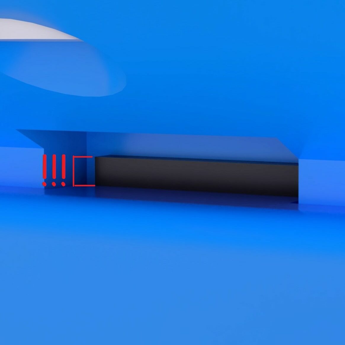
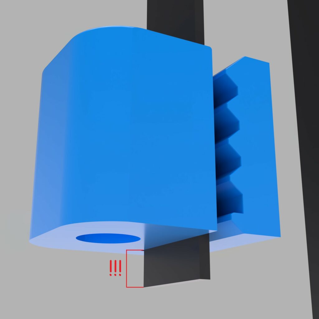
a) Route the Belt
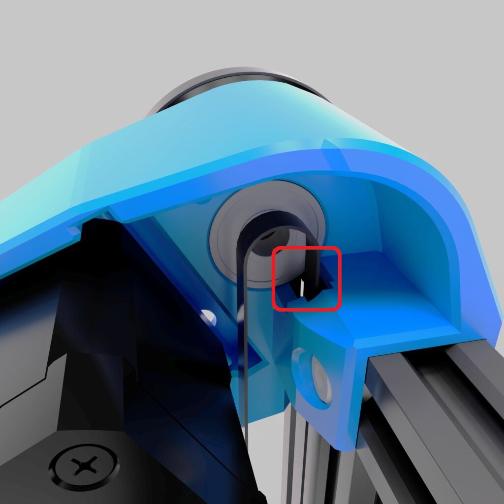
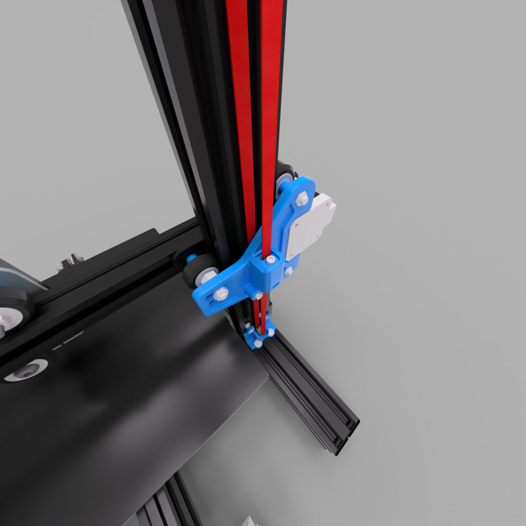
The installation of the belts requires a little more attention. Start by routing the belt as shown in the two pictures (the belt is colored red for clarity; hover over the image to zoom). The belt is routed around the top of the 20T, behind the plastic plates (between Z-profile and plates) down around the idler back to the plates. CAUTION: It is very very very important that both belts have the exact same length/number of teeth! If the belts do not have the same number of teeth, your Z axis will always run crooked, so take some time to make sure that both belts have the same length. I always put both belts with the teeth together and check that both belts are the same length. Note that in this way the belts are slightly offset, so at the top end, for example, the right belt is offset one tooth to the outside, then it must be offset one tooth to the inside at the bottom. If you cut the belts at a later time, make sure that you cut off the same number of teeth on both belts.
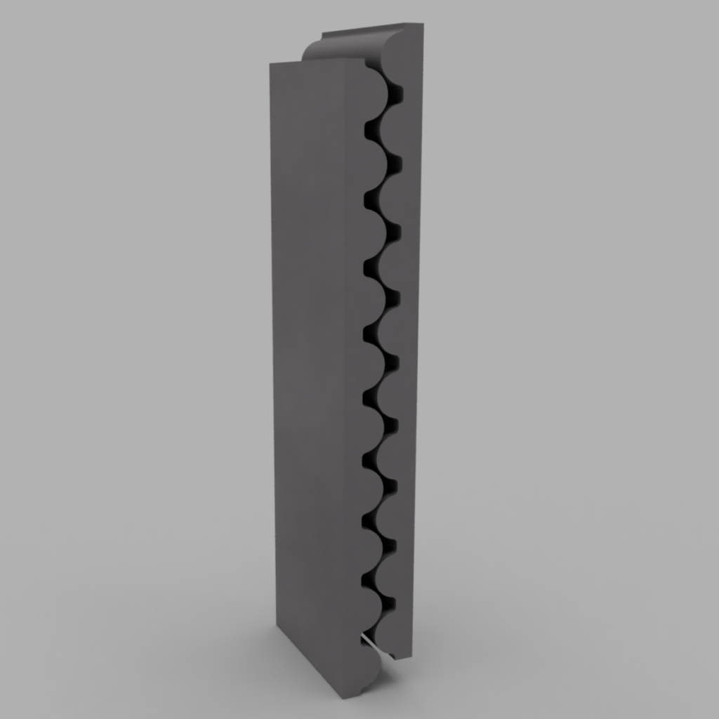
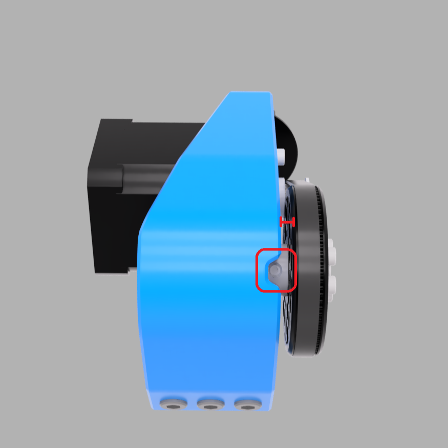
b) Fix the Belts
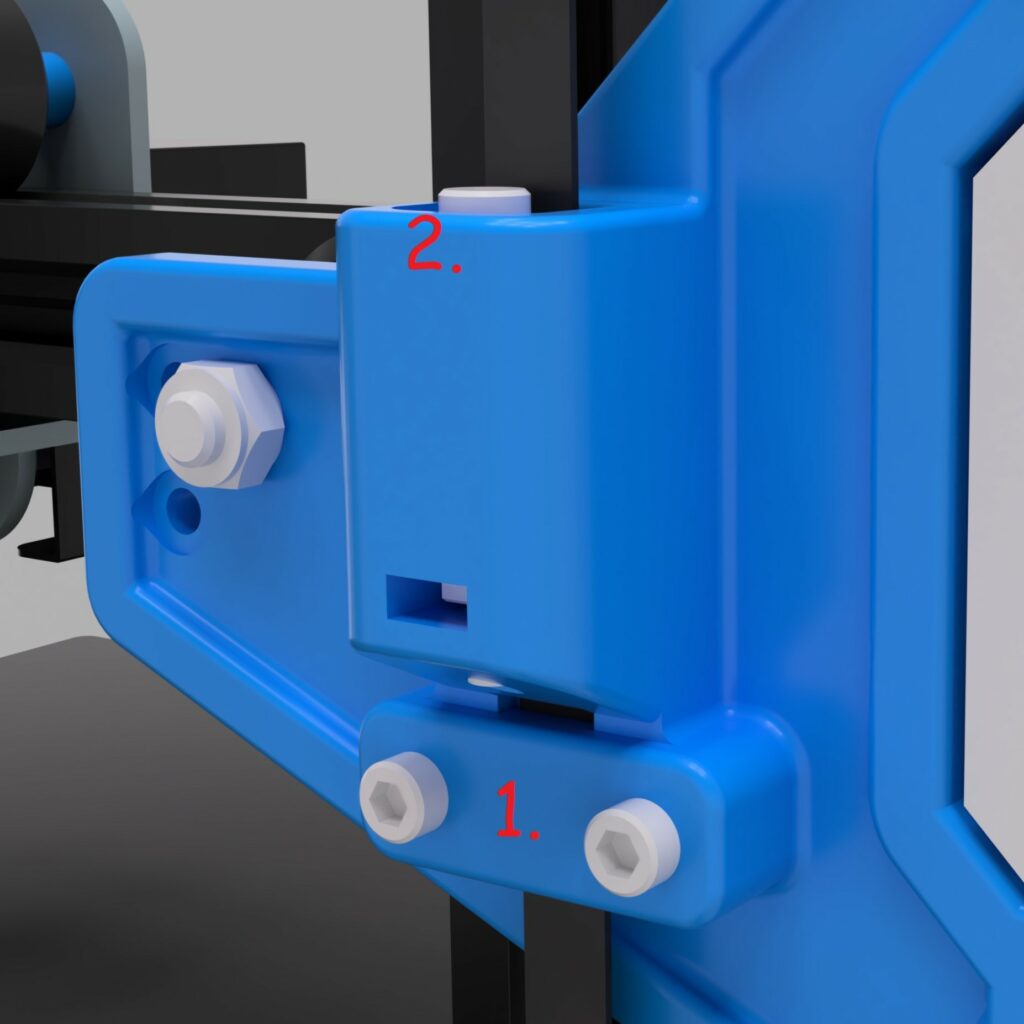
You’re almost there! After the belts have been cut to the same length and routed, they need to be fixed to the plates. Start with the lower clamp. Once again, it is very important that this step is identical on both plates. It is best to leave the belt protruding 1 tooth from the clamp so you can make sure the belt is fixed the same way on both sides. The clamp on the plate has a profile in which the belt can fit perfectly. Fix the belt with the clamp (2_TensionerClampV3.stl) and the two M3x12mm screws (we already used them when assembling the plate). If you forgot to insert the M3 nuts in the back of the plate, you will have to disassemble the plates again now.
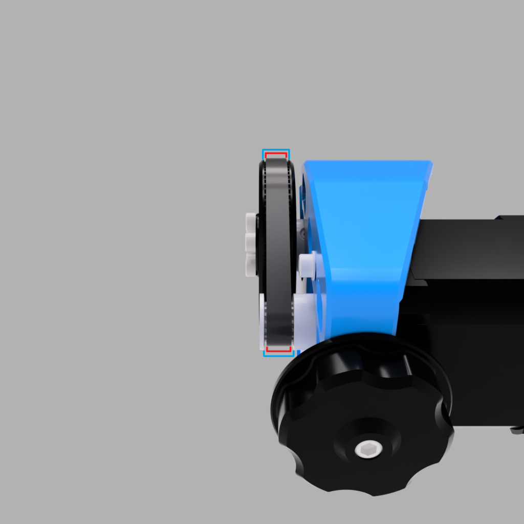
After the belt is fixed in the clamp the same way on both sides, put the tensioner block (2_TensionerBlockV3.stl) on the belt. Again it is very important that this is done in the same way on both sides! Leave a few teeth sticking out on the other side of the block. It is best if the block is flush with the housing for the tensioner block and the belt already has a slight tension. If you have too much belt left over, cut off the excess, but again identical for both sides! Do not insert the M3x25mm screw yet! We will come to that in the next step!
c) Tension Belts
This is a much discussed and requested point so I will explain step by step how I tension my belts. I have already mentioned how important it is that both sides are identical, and the same applies to the tensioning of the belts. I use an app for my phone for this, which app you use doesn’t matter (I use PanoTuner Free for IOS). These apps are meant to tune musical instruments, but you can also use them to tune the belts. For that you have to pluck belts like you would pluck a guitar string. The two belts will always sound different, that’s normal. This is because the x axis is not symmetrical and the side with the x motors (and the extruder motor if used) dampens the sound more than the side without motors. So don’t be misled by this and do not try to give both sides the same tone. Now proceed as follows:
- both sides: Insert the M3x25mm screws into the tensioner block and make sure that the M3 nut is in the tensioner housing on the plate.
- both sides: Insert the block into the guide of the tensioner block along with the screw. Make sure that the screw comes down to the nut. Now turn the screw counterclockwise as if you wanted to unscrew it. Push the screw down and turn it very slowly. You should hear a soft click at one point. At this point the screw has jumped over the start of the nut thread. As soon as you hear the click, turn the screw exactly two turns clockwise (tighten the screw). Note the position of your Allen key at the click, so that you know how the Allen key must be positioned again after two turns. There is no real tension on the belt yet, but the screw is screwed in equally on both sides.
- left side/side with the X- motor and extruder motor. Now it’s time for a little math. For all the following steps, use the left side as a reference (because it is damped from sound) . It is best to use the long part of the belt on the inside (between the plates and the Z profile), if you have trouble to pluck it (it shouldn’t touch the plates and the Z profile) you can also use the outer upper belt (the section from the 20T pulley to the tensioner block). For the second case, your Z / X axis should be as far down as possible, preferably in the homing position (just let the nozzle sit on the bed, the axis can not move yet, so homing is not possible).
As already announced, the belt is now adjusted via the sound when plucking. Important is the frequency (measured in Hertz) with which the belt vibrates. Which value the belt should have can be calculated very easily: (Source)Hertz = 28531 / mm
If measuring from the inside belt (the longest) on the Z axis belts, you would use 66hz on an Ender 3/Pro/V2. If you use the outer belt, the value will be different. Measure the length of the belt and use the formula above.
This value is the target to which the belt should now be tensioned. As already mentioned, the left side is used as a reference. Always measure the tone on this side only. Increase the tension of the belt by turning the M3 screw further clockwise (max. 1-2 turns between measurements, ~1/4 turns at the end). Copy the rotations you made to the other side. But do this step by step (eg. 1-2 rotation left, 1-2 rotation right, not 10 left and then 10 right). Again as a reminder, the two sides will sound/display a different Hertz value, this is normal! When the belts have reached the correct tension, move the axis up and down a few times (the motor should not rotate because the grub screws are not tightened yet). Then check if the tension is still correct, if not adjust it.
d) Tighten all the grub screws
Moving the axis up and down also aligns the 20T pulleys on the rod. When the axis has moved all the way up, both plates should be at the same height, or hit the frame the same on both sides (depending on the extruder, the axis may not be able to move all the way up on the Ultra-Low version, so make sure the distance is still the same). If the distance is the same on both sides and the belts in both 20T pulleys are about centered, you can tighten the grubscrews. Make sure the belts do not make contact with the plastic parts. (If your axis is not the same height, take a look at the end of this section).
The last step is to tighten the grub screws on the 80T pulley and the motor. Align the 80T pulley so that there is a small gap between the transmission body and the 80T gear. When you are satisfied with the position, tighten the grub screw from the 80T gear. The 16T pulley on the motor also needs to be adjusted. Loosen the grubscrew from the 16T Pulley and put the 188T looped belt around the 80T Gear and the 16T Gear. Turn the M5 screw in the tensioner knob until the belt has a slight tension. The belt should only have a very slight tension, not like the long belts. The tension is only to prevent the belt from slipping over the teeth! The motor should not be connected to the mainboard yet, if you have already plugged in the cable, pull it out again (Otherwise, the motor will cause reverse current flow and could damage the board (this is very board specific, be safe and unplug the cable)). Now move the axis up and down a few times. The 16T should now rotate on the motor shaft. If the motor turns, loosen the grub screw of the 16T pulley a little more. The 16T pulley will now align itself and the belt should center itself (If it doesn’t or if you hear a cracking noise, you have overtensioned the small 188T belt. Loosen the M5 screw again a bit). Once the pulley has found its position, tighten the grub screws again. All done? Not quite, the motor still needs to be connected to the mainboard.
Your axis is not the same on both sides? This happens from time to time and it’s not even your fault. The frame of the Ender 3 is not always straight and that shows here. There is not much you can do about it. If the difference is minimal, you can push the side that is too low up a bit so that both sides are at the same height. But this is only possible if the difference is minimal, otherwise you would add too much tension to the motion parts and they will wear out faster. It is also possible that the metal plates holding the X axis are not straight. The straight top edge of these plates must be level with/parallel to the x axis profile. If they are not, the X axis is crooked. The small M4 screws (which we already used when installing the plates / changing the screws) hold the plates tight. You can try to loosen these screws a bit and straighten the axis. But be careful.
e) Wiring
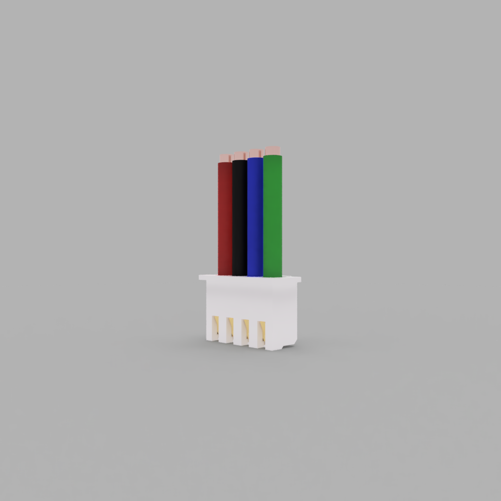
The last thing to do is the wiring. The picture shows the order of the cables as they have to be for the original mainboard and the original motor with the cable I linked in the BOM. However, cables, motors and mainboard are not the same for all of us and your motor may not move correctly (not at all or in the wrong direction). The correct and safe way would be to find a pin-out diagram for your mainboard and motor and arrange the cables accordingly. Since there are many differences, I will not show diagrams here, but rather show you the basic troubleshooting. To rearrange the pins you need a tiny screw driver or a pair of tweezers to press down the metal pin in the connector. ATTENTION! If motors are connected incorrectly it can cause damage to the printer. I recommend to check for the mentioned pin-outs and to make the connection properly.
I) The motor only vibrates very strongly, but does not move.
There are two coils in the motor which are alternately supplied with current and thus turn the motor. In this case you have connected the motor wrong, so that both or no coil gets current. Swap the middle two cables for this. If the motor still vibrates, also swap the two outer cables (one of them has been moved twice now).
II) The motor/axis is moving in the wrong direction.
The order of the cables is correct, but unfortunately it is the wrong way round. Either you change the direction in the firmware or you turn the connector around. If you use Klipper just put a ! in front of the dir_pin, or remove it if there is one:
[stepper_z]
[…]
dir_pin: PA0  <-> dir_pin: !PA0
[…]
If you use Marlin it is much more complicated to change the firmware, so I recommend you to simply reverse the connector. For this the pins have to be in the reverse order in the conntector (1234 becomes 4321):
Now you did it! Congratulations 😀
I hope you enjoyed the build and the instructions were understandable. I would be very happy if you would send me some feedback on my Discord server.

It is very important to me that all my projects are free and open-source. But if you want, you can support my work. All designs are free and will remain so, so please don’t feel forced to donate anything 🙂