Requirements:
– Autodesk Fusion 360 account (Free personal license is fine)
– Autodesk Fusion 360 installed
1. Open the CAD file
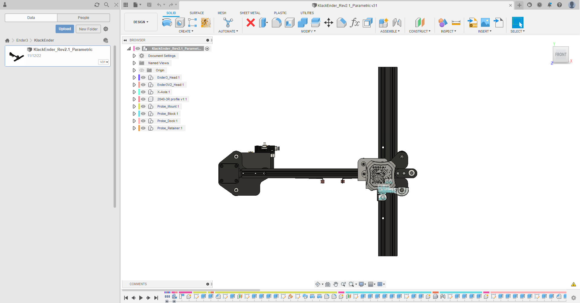
First you have upload the file to fusion. Simply double click on the file or upload it to the browser in fusion on the left side (once you opened a folder e.g. ‘My First Project‘ there’s a small blue upload option at the very top). Then open the file, it should look close to this:
2. Open the parameters tab
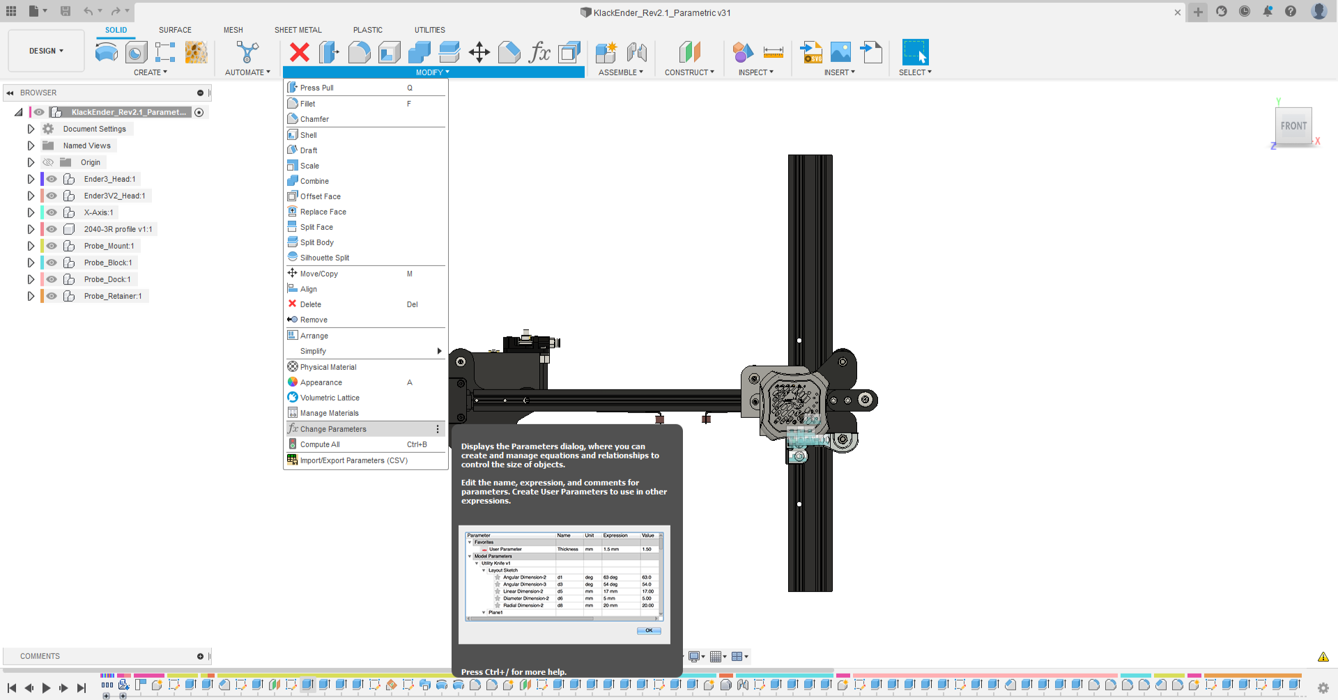
Click on Modify > fx Change Parameters and fusion opens a new window. In there you an find all the parameters / variables you can adapt to get this design compatible with your printer. With these you can go way beyond the Basic-Check-Variables to adapt the design. You can find a list with all variables at the end of this page.
3. Change the parameters
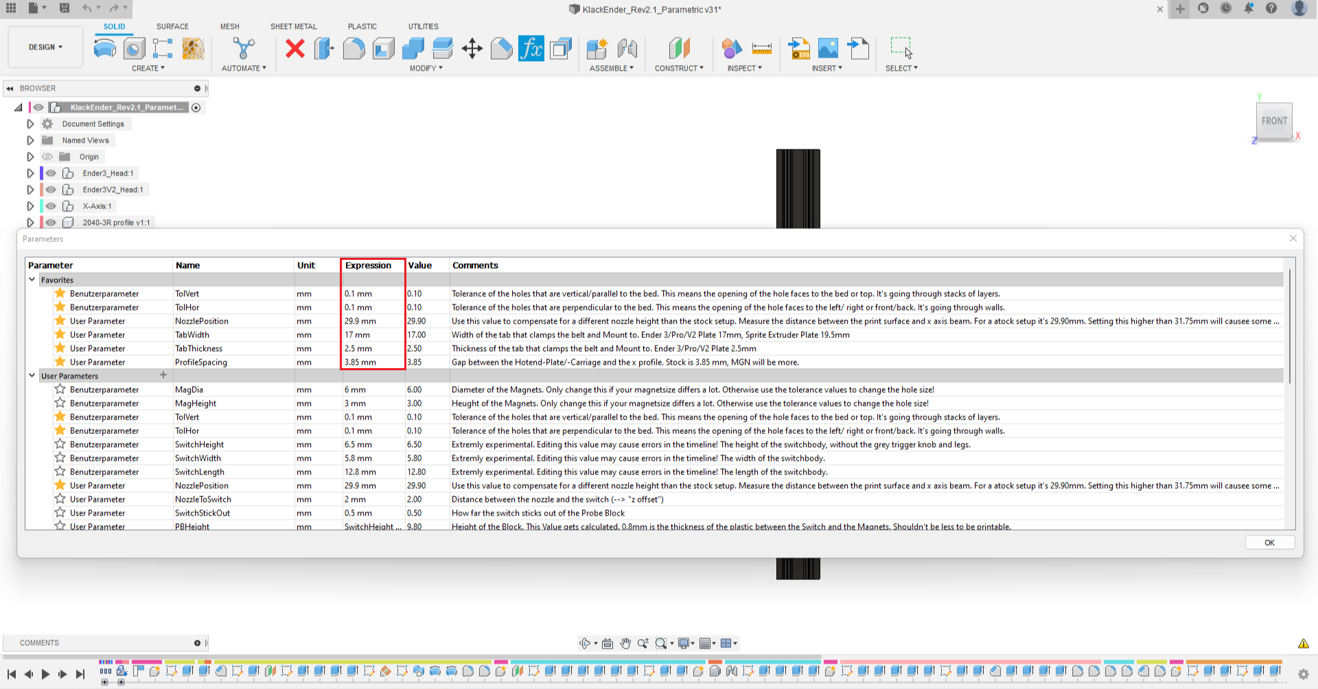
You will find a long list with many variables to adapt the design. At the top you will find the Favorites tab where I placed the most important parameters. In order to change a value simply double click on a value in the Expression column. Once you’ve made your changes click OK in the bottom right corner. The design adapted accordingly.
3.1 Fix features in timeline
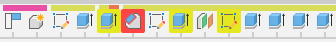
Parametric design is powerful, but not perfect. There are many dependencies in the design that can cause problems when parameters are changed. I have done several tests with the Basic Check Variables, but nothing is perfect. However, most failed features are just cosmetics like fillets or chamfers, and the design should still be functional. There are two types of errors: yellow and red. Yellow means that something has changed. The feature still works, but it’s worth checking to see if the program transferred it correctly. Red means a failed feature because something is missing, for example, an edge for a chamfer or a profile for an extrude. While you will most likely do not need to fix the yellow errors, you will need to fix the red errors. To do this, double-click on the feature in the timeline and try to get things right. If you’re not sure how the feature should look, open an unmodified version of the Klack and use that as a reference.
4. Export your new STL
Now all that’s left is to export the new STL file. Therefore simply right click on the part you want to export. Select Find in Browser and the Browser at the left will expand to the body you just selected. Right click on that again and select Save as Mesh. Maybe you have to change the file format from 3MF to STL, if you want to. Just click OK for the dialog and save the file on you PC. That’s it!
| MagDia | 6 mm | Diameter of the Magnets. Only change this if your magnetsize differs a lot. Otherwise use the tolerance values to change the hole size! |
| MagHeight | 3 mm | Height of the Magnets. Only change this if your magnetsize differs a lot. Otherwise use the tolerance values to change the hole size! |
| TolVert | 0.1 mm | Tolerance of the holes that are vertical/parallel to the bed. This means the opening of the hole faces to the bed or top. It's going through stacks of layers. |
| TolHor | 0.1 mm | Tolerance of the holes that are perpendicular to the bed. This means the opening of the hole faces to the left/ right or front/back. It's going through walls. |
| SwitchHeight | 6.5 mm | "Extremly experimental. Editing this value may cause errors in the timeline! The height of the switchbody, without the grey trigger knob and legs." |
| SwitchWidth | 5.8 mm | Extremly experimental. Editing this value may cause errors in the timeline! The width of the switchbody. |
| SwitchLength | 12.8 mm | Extremly experimental. Editing this value may cause errors in the timeline! The length of the switchbody. |
| NozzlePosition | 29.9 mm | Use this value to compensate for a different nozzle height than the stock setup. Measure the distance between the print surface and x axis beam. For a atock setup it's 29.90mm. Setting this higher than 31.75mm will causee some calculation errors for the fillets. Ignore them or modify the element in the timelime. |
| NozzleToSwitch | 2 mm | "Distance between the nozzle and the switch (--> ""z offset"")" |
| SwitchStickOut | 0.5 mm | How far the switch sticks out of the Probe Block |
| PBHeight | SwitchHeight - SwitchStickOut + 0.8 mm + MagHeight - MagStickOut | Height of the Block. This Value gets calculated. 0.8mm is the thickness of the plastic between the Switch and the Magnets. Shouldn't be less to be printable. |
| PBWidth | SwitchLength + MagHeight + 2 * MagWalls | Width of the Block. This Value gets calculated |
| MagWalls | 3 mm | Wallthickness around the magnets |
| WireDia | 2.5 mm | Diameter of the wires that go into the magnetpockets on the mount. |
| M3HeadDia | 5.6 mm | Head Diameter of M3 !!SHCS!! |
| M3HeadHeight | 3 mm | Head Height of M3 !!SHCS!! |
| MagStickOut | 0 mm | Stick out distance of the Magnets (in the probe block) to get better contact if needed |
| MagSpacing | 10.16 mm | I know it's an odd value but this is the spacing of the Magnets for Rev1 and Rev2. In order to keep all parts interchangable I set this value here. Modify sketch Nr. 2 and change this value to PBWidth to get design thats fully calculated by the magnet sizes and the wall whicknesses. |
| XAxisClearance | 0.5 mm | Highly experimental. Cearance between the top of the Klack Mount and the x Axis profile. Don't set a value greater than 1.5 or the mount will be too unstable and unprintable. |
| M3BiteMetal | 0.125 mm | This value sets thee distance between the side M3 and the Metal tabs on the X carriage. |
| TabWidth | 17 mm | Width of the tab that clamps the belt and Mount to. Ender 3/Pro/V2 Plate 17mm, Sprite Extruder Plate 19.5mm |
| TabThickness | 2.5 mm | Thickness of the tab that clamps the belt and Mount to. Ender 3/Pro/V2 Plate 2.5mm |
| ProfileSpacing | 3.85 mm | Gap between the Hotend-Plate/-Carriage and the x profile. Stock is 3.85 mm, MGN will be more. |