Below you will find a list of all the parts you need to build the Mod. The links for the print files will take you to my GitHub, where you can download all STLs in a zip. Below the listing of the needed parts and files you can start with the build instructions. I have tried my best to make everything as easy to understand as possible. If you still have any questions feel free to join my Discord. Please open a new topic in the help forum and add as many information as possible to your request. That’s helps a lot with the troubleshooting!
Bill of materials:
Hardware parts you need:
| Category | Component | Quantity | Reuse from Printer? | Notes | Source |
|---|---|---|---|---|---|
| Electronics | OMRON D2F | 1 | no | Buy exactly this switch! There are many versions of it, e.g. OMRON D2F-L, it doesn't matter. As long as the switch has the designation OMRON D2F, it is fine. Also, buy from trusted vendors and don't take the cheapest offer from a random store. There are many clones out there that are unusable for the Klack. | DFH.fm (US) |
| Cable | 1-2 meter 22awg wire | yes/no | For wiring the Klack. Maybe you have a fan- or motorwire left. | ||
| Crimp connectors | 1 | no | You have to connect the Klack to the mainboard somehow. The type of connector depends on your mainboard (Stock, SKR Mini E3: JST-XH 2 pin). You may be able to reuse the stock z-endstop cables for that with some soldering. | ||
| Fasteners | M2x10mm self tapping | 2 | no | ||
| M3x10mm | 1 | no | SHCS or BHCS doesn't matter, to fix the Mount to the Metal Tab. | ||
| M3x12-16mm | 1 | no | SHCS or BHCS doesn't matter, for the Probe Dock. | ||
| M5x8mm | 2 | No | SHCS or BHCS doesn't matter. | ||
| M5 T-nuts | 2 | no | |||
| M5x45mm | 1 | yes/no | For users of the Belt Z Mod: With the V-Wheels the 40mm screw is just long enough, for the MGN it's too short. All others: The stock screw is fine. | ||
| Misc | 6x3mm Magnets | 6 | no | Blank/no anodized Magnets! Try to get some good quality magnets, they shouldn't be too weak. But you should not overdo it with the strength of the magnets either. Magnets up to 900g work well. | |
| Small Zip-Tie | 1-2 | no | To do some cable management. | ||
| Filament | Petg or ABS (+) | no | Do not use PLA! The Klack_Mount might be the only part that works in PLA, all other parts are near heating elements. PETG is totally fine. |
Vendors
Note: The Kits are highly recommended! With the kits you get tested and matching parts.
With your help, my mods has grown bigger than I could have ever dreamed! I am very happy that also this mod has a great vendor selling kits:
DFH.fm (US based)

STL-Files
Basic checks:
1. Tolerances
Okay, I know you’re very excited to hit the print button, but before you can start to print the files you have print a little test. The Klack is based on a press-fit-design, which means you have to know the tolerances of your printer. This sounds much more complicated than it is. Just print the small test part to see which tolerances you need. In case even the 0.3mm tolerance is too tight, you should take a step back and start with some printer tuning.
The STL for the test is part of the Zip you can download in the next section a little further down, but you can also get it from my GitHub.
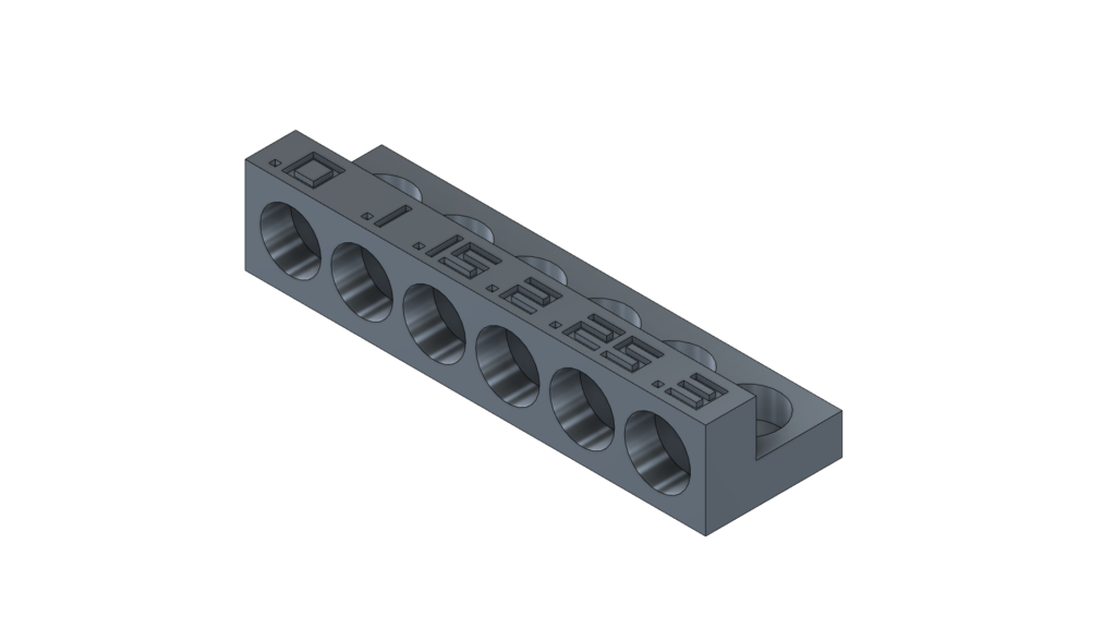
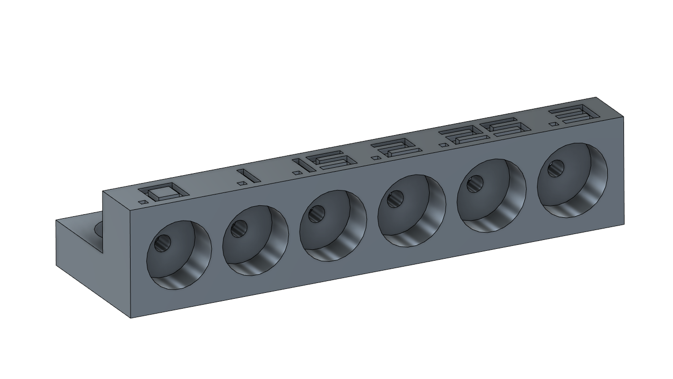
Why do I have to print the test file?
Some of you have contacted me with the problem that the layers split when they insert the magnets. This happens when the magnet is too big for the hole/the hole is too small for the magnet. So either the magnets are a bit bigger than 6mm or your printer prints the holes too small (never use a caliper to measure the magnets!. Only if they are made of plastic!). How the printer prints the holes depends not only on the material (ABS shrinks a bit, while PETG stays fairly constant) but also on the orientation of the holes. Vertical holes are usually a bit smaller than the horizontal ones - the ones that are printed in the walls. This is because these holes are formed by the layers and can never be completely round (the circle is made of 0.2mm (layer height) lines). At the same time, the diameter is strongly influenced by the print settings (speed, acceleration, linear advance/pressure advance, etc.).
However, you may need different tolerances than I do. That is why I have designed the small tolerance test (thanks to SchlongkyDong for the idea!). As already described, the tolerances for vertical and horizontal holes can/will differ. Stick a screwdriver through the smaller holes to get your magnets out again.
2. Compatibility
If you’re using an Ender 3 (V1, V2, Pro) with the stock Hotend-Plate, stock hotend or a replacement that has nearly the same length (e.g. Dragonfly BMS) you can skip this section. If you did any modification to your hotend-assembly or you’re using an Ender 3 Clone, you should invest the 3 minutes to check some basic measurements. If you’re measurements are different from the ones mentioned here take a look at the next section CAD Instructions – Create your own STLs!
Hover over the image to zoom.
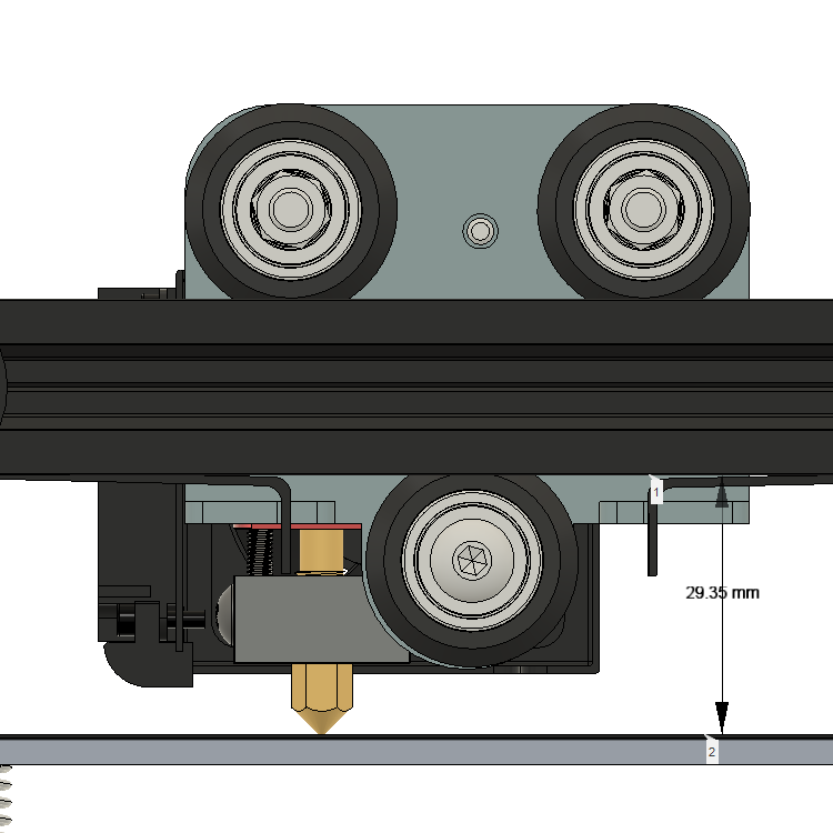
Place your nozzle on the bed-surface (the nozzle should be cold so nothing melts – also moving the bed all the way to the front makes it easier to measure the distance). Measure the Distance between the bed-top-surface and the underside of the x-axis profile. For a stock Ender 3 this should be ~29mm.
< 29mm:
29-31mm:
> 31mm:
Totally fine.
Also fine, your z_offset will be very small.
The nozzle sits too low and will touch the build plate before the probe.
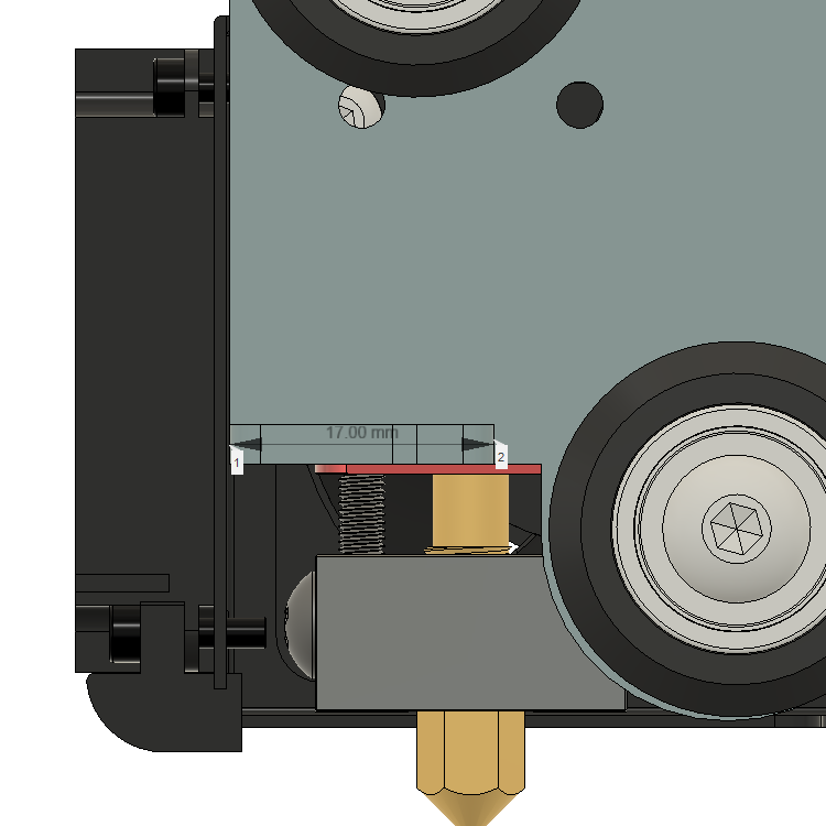
Maybe you have to remove the belt to measure this. The Tab-Width for an Ender 3 is 17.00mm.
<= 17mm:
> 17mm:
Totally fine.
The Probe_Mount will not fit on the tab
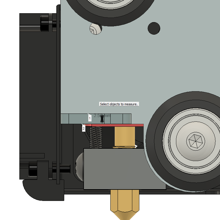
Maybe you have to remove the belt to measure this. The Tab-Width for an Ender 3 is 2.50mm.
< 2.3mm:
2.3-2.7mm:
> 2.7mm:
The Probe_Mount will be ttoo loose.
Okayish to tight press fit
The Tab is too tick and may/will split the Probe_Mount.
STL-Download: Click on the tolerance-combination you need
Thanks to HarryPulvirenti from my discord for exporting all the STLs!
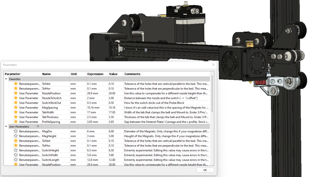
CAD Instructions – Create your own STLs!
As already mentioned the provided CAD file is based on parameters. This way it should be very easy do adapt the parts for your needs. If you want to see how that works click on the picture below:
Build Instructions
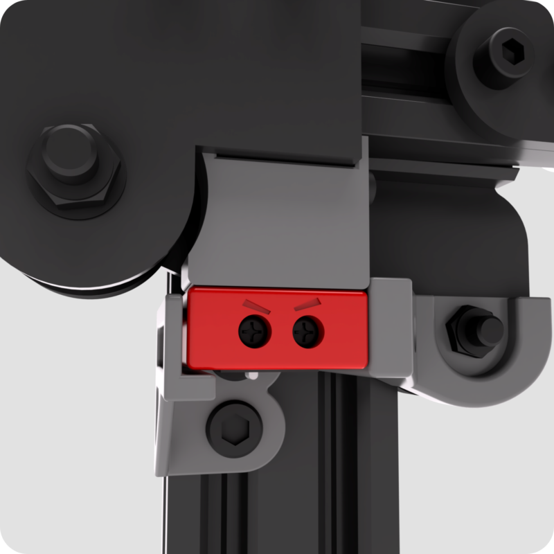
The picture shows all the assembled and mounted Klack parts. The build is divided into individual chapters which you can select by clicking on the image. Just click on the section you want to build. The instructions will open in a new tab, so after you finished the chapter you can select the next one on this page.
I recommend to start with the probe block.