Note:
– Never apply any pressure/force onto the switch body! When pressing in the magnets use the printed part to press on, not the switch itself! Otherwise you will break it!
– If your magnets have a too loose press fit, you probably chose the wrong tolerance. If you have really big problems keeping the magnets in place, you can glue them down with some epoxy.
1. Switch preparation
a) Removal of the leveler arm
An Omron D2F-L (L=Leveler) has a leveling arm attached. To remove this, use a pair of pliers to squeeze the lower side of the leveling arm. In this way, you can easily remove the leveler. If your switch comes without a leveler, you can skip this step.
b) Cut off the middle leg
You can set up a switch in two ways: normally open or normally closed. We want to set it up as normally closed, so we need to use the two outer arms of the switch. Just cut the middle arm with the flush cutter that came with your printer. It doesn’t have to be perfect, all it needs to be is roughly flush with the switch housing.
Switch Science – Normally open / normally closed – what does that mean?
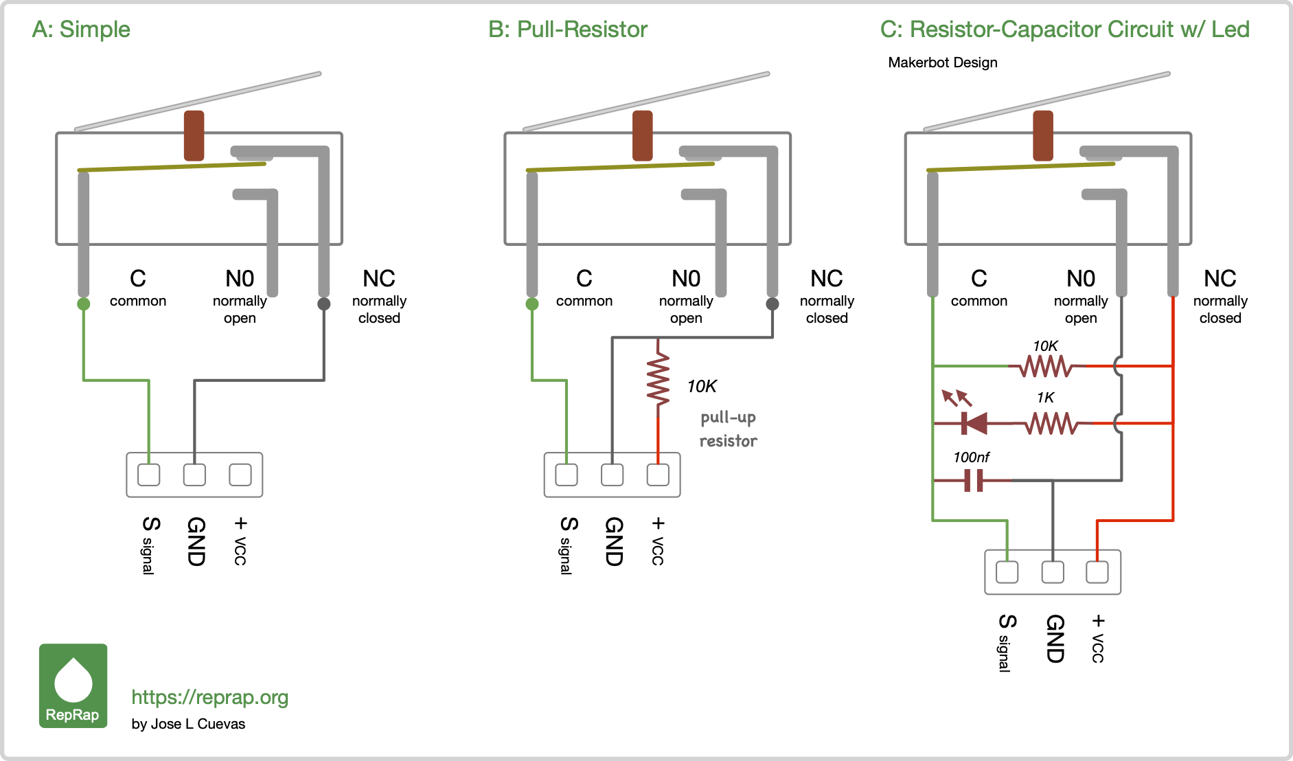
Source: RepRap
In case you are interested, I would like to take this opportunity to explain how the Omron switch works – it makes troubleshooting a little easier. If you look at the schematic, the switch is connected with wires to two pins on the main board (signal and GND). As I said, there are two ways to configure the switch, depending on which arms you use:
1. Normally closed – the outermost arms: ‘Normally’ means the state when the switch is not triggered. So a normally closed switch that is not triggered behaves like a wire connecting the two pins on the main board. By triggering the switch, the two pins are no longer connected, the switch is now open. Releasing the trigger again closes the switch and thus the connection again.
2. Normally open – left arms: Like the normally closed setup, but with inverted logic. So the switch must be triggered to close the connection between the pins. This is also why this is a very unsafe way to set up a switch for a limit switch or probe. If you have already assembled the Probe_Mount, you may understand this a little better. The wires that go into the mount are in contact with the two magnets, but the magnets themselves are not in contact. So there is no connection between the two pins on the motherboard aka the connection is open. Adding a normally open configured switch doesn’t change anything, the pins are still not connected. Therefore, we want a switch that is normally closed. When the switch is connected, the connection between the pins is closed and the printer knows that the switch aka the probe is connected.
3. Connecting the right arms just makes no sense because the switch state (triggered/not-triggered) can’t change.
2. Switch Installation
a) Probe_Block preparation
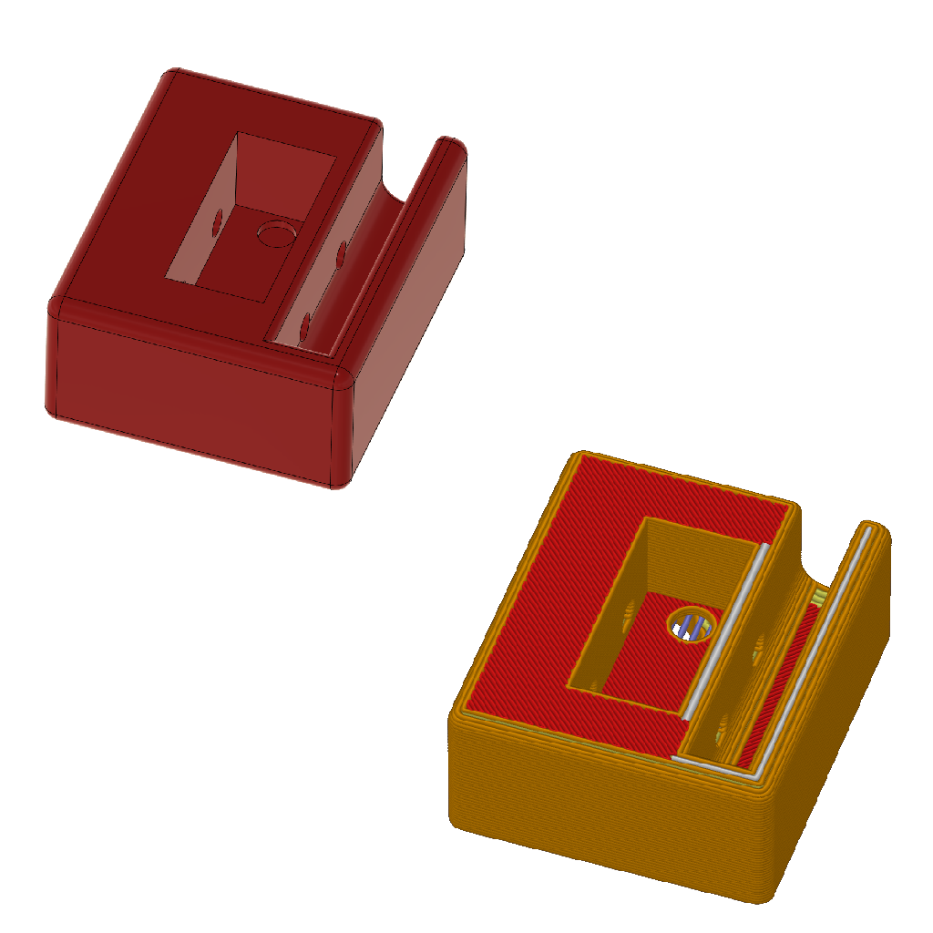
The two small holes for the switch legs are closed and need a little clean up. This is on purpose and helps with bridging ( you can see the little blue lines on the sliced preview – hover over the image to zoom in). Use a small Allen key or something similar to push through the hole. Remove all excess parts from the switch housing and magnet pockets on the other side.
b) Switch installation
So now the holes are cleaned up, then the switch can be installed. I like to have the trigger as close as possible to the nozzle. Therefore, I install the switch with the trigger to the left. Make sure the mounting holes in the switch body line up with the eyes of the Probe Block, and that the switch legs are (almost) flush with the top of the block. Once the switch is in place, secure it with two M2x10 (self-tapping) screws.
3. Magnets insertion
If you assembled the Probe_Mount or Probe_Dock already make sure to insert the magnets the right way around so the magnet polarity matches!
a) First magnet
When inserting the magnet, make sure that you do not apply any pressure on the switch, but use the printed block to press the magnets in. To insert the magnets more easily, you can tilt them very slightly in the direction of the switch legs. But in the end it is very important that the magnets are parallel to the block (they would not be perfectly flush with the block) – more about this in the next step.
b) Second magnet
Place the second magnet on top of the already inserted one. Lift it up again, turn it 180° and insert it into the probe block like this. You can insert it at a slight angle, as you did with the first magnet. The magnets will not be flush with the block, but in the end it is very important that both magnets are on the same level and aren’t crooked. Use the picture below as a reference to check if your magnets are ok.
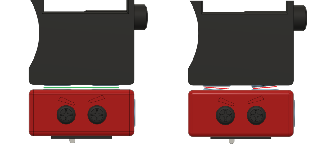
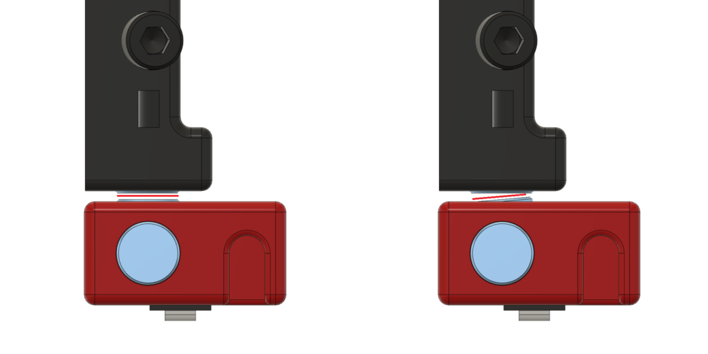
Magnet-Alignement-Check
The Image below show the probe block from the front and from the right. Use these to check the alignment of the magnets.
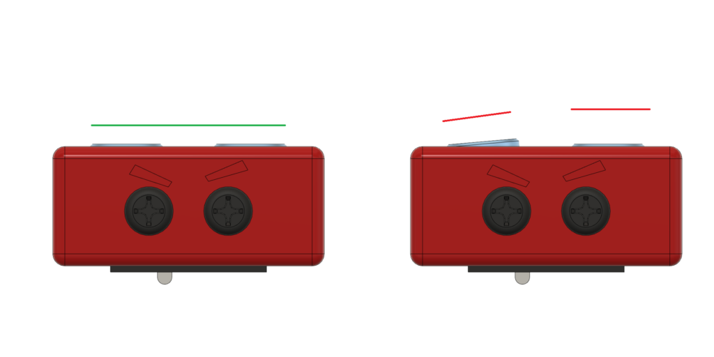
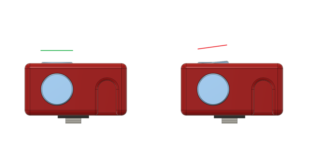
If you assembled the probe mount already check the alignment against that as well.
c) Third magnet
The thrid and last magnet belongs into the side of the Block. If you assembled the probe dock already make sure the polarity matches.