Note:
– I recommend to build the Probe Block first.
– If your magnets have a too loose press fit, you probably chose the wrong tolerance. If you have really big problems keeping the magnets in place, you can glue them down with some epoxy.
1. Mount assembly
a) Wire preparation
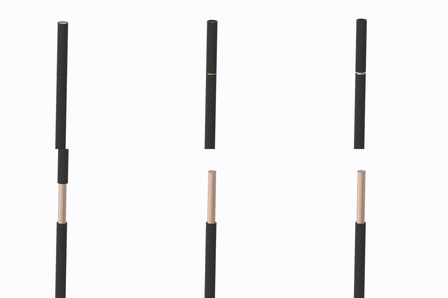
This method is a little different from the one I showed you in the Video about the Rev1. Remove 10-15mm of isolation of the wires. Try to not twist the wire so it takes less space in the magnet hole/pocket.
b) Wire installation
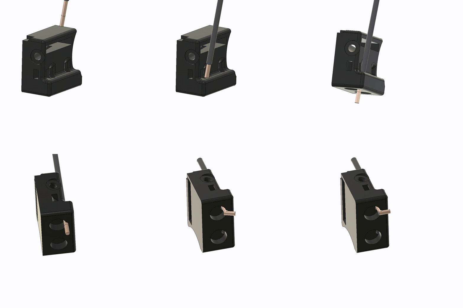
Route the wires through the little holes on the back of the probe mount and all the way through the magnet hole. Make sure the start of the isolation sits in the back of the Probe Block so nothing can short out. Once the wires are in place fold them over the walls of the magnet holes. This way the wire can’t move out again while pushing in the magnets. Do this for both sides.
c) Magnet insertion
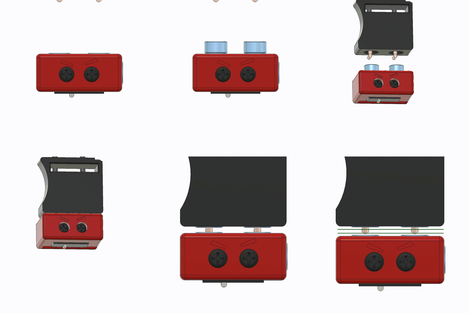
As I wrote at the beginning, I recommend assembling the Probe Block first. Once you have done that, you can use it to align the magnets. The side with the face of the block is aligned with the bottom of the holder (the side with the little arrow on it). Simply place the magnets on the Probe Block and press them in with the block. Again, press on the printed part, not on the switch! If you use the Probe Block to press the magnets in, you will get a nice and flush connection between the holder and the block. If you inserted the magnets the wrong way around you can get them out again by pushing a very very small allen key / screwdriver through the small holes you fed the wires through. This might damage the wire but simply redo the first steps.
d) Cut off wire excess
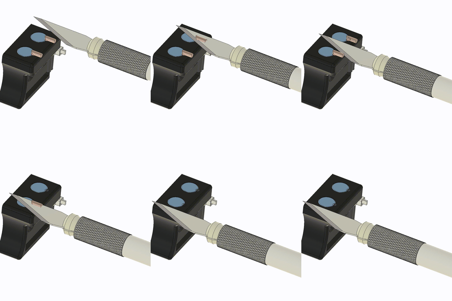
As the wires stick out, you will need to cut off the excess. It doesn’t have to be perfect, just make sure the wire doesn’t stick out past the magnets. You can use the flush cutter or an exacto knife to cut the wires. Be careful not to damage anything or hurt yourself. Now the wires are in place you can fix them with a zip-tie.
Confirm your work – wire connection
Now that the probe mount is not mounted yet, it is easier to check the work you have done. If you did it the way I described above, it is very unlikely that there is no connection between the wires and the magnets, but take this opportunity to confirm your work – you will need a multimeter for this. If your multimeter does not support the connection test (it usually beeps), you can use the function to measure the resistance. Put one tip on the magnet and the other on the corresponding end of the wire – if the multimter shows a resistance there is a connection. This can also help to check if the crimping of the mainboard connector was successful.
2. Mount installation
a) Mounting
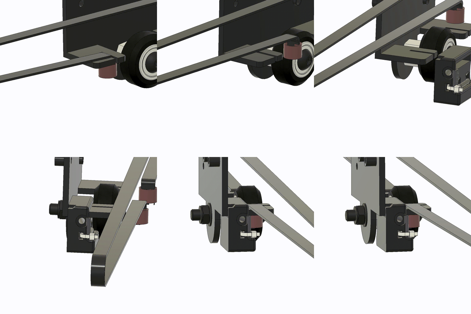
Compared to Rev1 and Rev2.0, it is no longer needed to take the carriage off the X-axis. You only have to loosen the tension of the belt and remove it from the right clamp. Then you can slide on the probe holder. It should already have a light press fit, the mount will be fixed in the next step.
b) Fix it with the screw
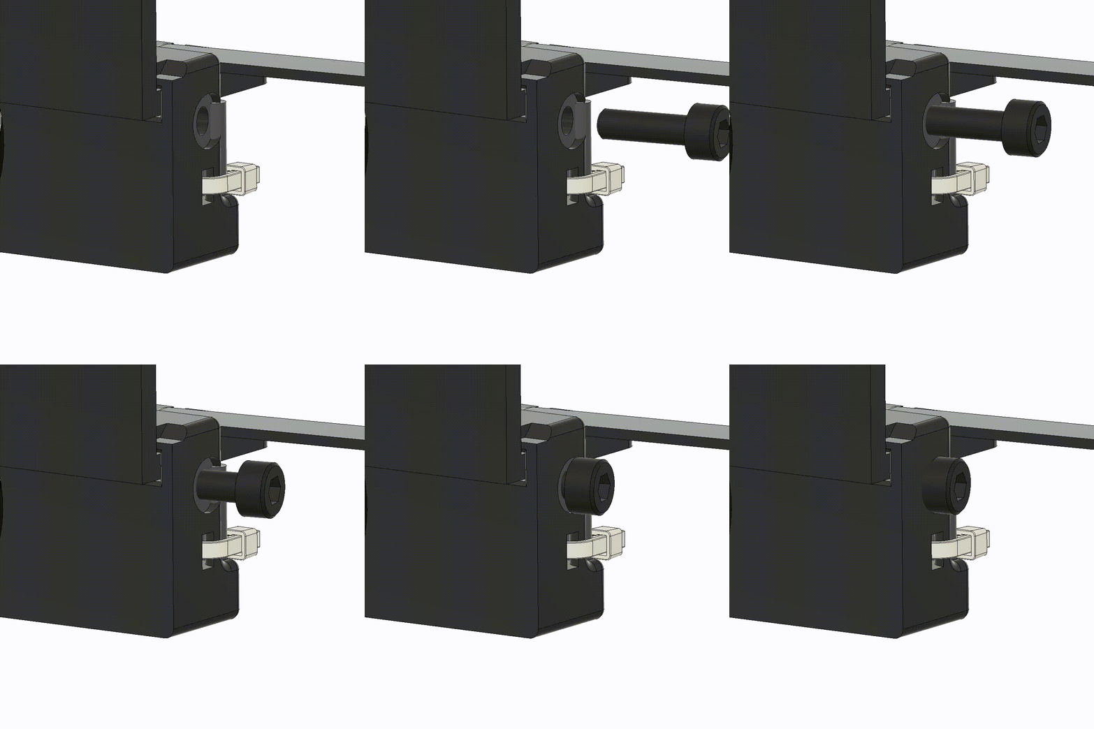
Use an M3x10mm screw to secure the mount. The thread of the screw will slightly bite into the metal of the plate. This may cause some cosmetic damage, but nothing that will affect the strength of the plate. Also, the screw is threaded in at an angle to provide a better hold in the X-Y plane. If you haven’t done already reinstall the x-belt.
